
PnP Solvers Explained: Why Four Points, and Why Corners Matter So Much
What a Perspective-n-Point solve is actually computing under the hood, why three points isn't enough, and why every post on this blog about marker accuracy keeps coming back to corner localization.
Last post ended on a claim I made without unpacking it: that ArUco markers use four corners because that’s exactly what a PnP solver needs to compute a pose. This post is that unpacking, what a Perspective-n-Point solve is actually doing, why three points isn’t enough, and why corner accuracy ends up mattering more than almost anything else in the pipeline.
The problem PnP solves
Perspective-n-Point, PnP, takes camera projection and runs it backwards. Forward projection is easy to state: given a camera’s pose (where it is, which way it’s pointing) and a set of known 3D points, predict where each point lands in the 2D image. PnP inverts that: given the camera’s known intrinsics (focal length, principal point, lens distortion, all fixed by calibration) and a set of correspondences, each a known 3D point paired with its observed 2D position in the image, solve for the unknown pose that would have produced those observations.
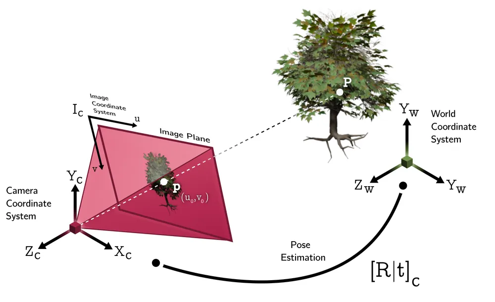
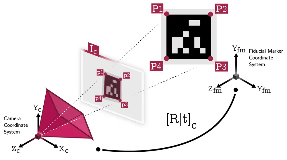
That’s it. A marker’s four corners have known positions in the marker’s own coordinate frame (it’s a flat square, you designed it), and a detector finds their pixel positions in the image. PnP is the step that turns those eight numbers (four 2D points) into a full 6DoF camera pose.
Why three points isn’t enough
A rigid 3D pose has six degrees of freedom: three for rotation, three for translation. Each point correspondence contributes two constraints, its observed x and y image coordinates. Three points, naively, give six equations for six unknowns, which looks like exactly enough.
It isn’t, because those equations aren’t linear. The relationship between a 3D point, a camera pose, and its 2D projection involves perspective division, and solving the minimal three-point case (known as the P3P problem) reduces to a quartic polynomial. A quartic can have up to four valid real roots. Geometrically: given only three points and the angles between them as seen from the camera, there can be as many as four distinct camera positions that are all equally consistent with those observations. Three points narrow the space of possible poses down to a small set of candidates, not down to one answer.
A fourth point is what breaks the tie. You take each of the (up to four) P3P candidate poses, check which one correctly predicts where the fourth point actually landed in the image, and discard the rest. That’s why OpenCV’s solvePnP refuses to run on fewer than four points: below four, the geometry is fundamentally ambiguous, no amount of numerical cleverness resolves it, because the ambiguity isn’t noise, it’s baked into the equations themselves.
This is also, not coincidentally, why a square marker has four corners and not three. It’s the smallest configuration that yields one unambiguous pose. OpenCV even ships a solver mode built specifically around it, SOLVEPNP_IPPE_SQUARE, tuned for exactly this case: four coplanar points in a known square arrangement.
import cv2

# object_points: the marker's 4 corners in its own flat coordinate frame
# image_points: their detected pixel positions in the current frame
success, rvec, tvec = cv2.solvePnP(
    object_points,
    image_points,
    camera_matrix,     # intrinsics from calibration
    dist_coeffs,        # lens distortion coefficients
    flags=cv2.SOLVEPNP_IPPE_SQUARE,
)What more points actually buy you
Anything beyond a single flat marker, a full 3D fiducial object, a checkerboard, a calibration rig, hands the solver more than the minimal four points. Past the minimum, extra points stop being about disambiguation and start being about averaging out noise. A common approach (EPnP) expresses every 3D point as a weighted sum of four virtual control points, then solves a much smaller linear system for those control points’ positions in the camera frame, sidestepping the combinatorial blow-up of the exact minimal case entirely. An iterative refinement pass afterward (typically Levenberg-Marquardt, minimizing total reprojection error across every point) then polishes the estimate.
Every additional accurate correspondence pulls that least-squares solution closer to the true pose. It’s the same reason combining detections from multiple faces of a fiducial object measurably outperforms any single flat marker in my own results, more independent, accurate points feeding the same underlying solve.
Why corner accuracy matters so much
With a minimal four-point marker, there’s no averaging cushion. Every one of those four corner detections has direct, outsized leverage on the final pose, there’s no fifth or fiftieth point around to dilute a bad one. A 1-pixel corner localization error doesn’t stay a 1-pixel error once it propagates through the solve: because PnP is inverting a perspective projection, that same pixel error maps to a larger real-world positional error the farther the marker sits from the camera (fewer pixels per real-world centimeter at range), and a larger rotational error the more oblique the viewing angle (foreshortening compresses the corners together in the image, so a fixed pixel error represents a bigger fraction of the observed geometry).
That’s the actual reason marker-detection pipelines bother with subpixel corner refinement after the initial coarse detection, fitting a local edge or gradient model instead of trusting the first estimate. And it’s the same reason the calibration step in my Fiducial Objects work exists at all: a 3D-printed marker’s real physical corners never perfectly match its digital design, and that mismatch feeds into the exact same PnP solve as if it were ordinary detection noise. It has to be measured and corrected before the pose estimate can be trusted.
The takeaway
Every fiducial-marker system I’ve written about on this blog, ArUco, the custom fiducial objects from my thesis, comes down to the same core operation: turn a handful of accurately-localized 2D-3D correspondences into a 6DoF pose via PnP. What actually differs between them is how many points they hand the solver, how precisely those points can be localized, and from how many viewpoints at once, not what happens once those points reach the solver itself.